Wednesday, June 20, 2012

Gauges! Pt. 1

Gauges.  I've got five in all, and I think three need something above and beyond the call of duty done to help them (besides a new paint job).

Fuel gauge:  needs to be opened up and hopefully just solder a few wires together
Speedometer:  repair/replace one of the mounting screws on rear
Amp gauge:  OK?  Hurrah!
Oil gauge:  OK?  Hurrah!
Temperature gauge:  Aye, carrumba.  This will take some work...and then it probably still won't work.

So lets jump right in and fiddle around with the fuel gauge.  The first step is to check the resistance between the two poles.  They checked out alright.  However, when I checked the resistance between the driver's side pole (facing), I came up with an infinite reading.  That is not alright.  Time to disassemble and investigate.
Resistance between the poles:  CHECK.

Resistance between pole and base:  Not so good.

I used a paint lid pry bar (like a bent screw driver) to get the lip of the cover going and then a screwdriver finished the deal.

The last two nuts then were removed.  I sprayed a tiny drop of penetrating oil into the center of each.  Then, very carefully so not to have the post spin, I unscrewed each nut.

The internal part gauge needed to be slightly persuaded, but it did eventually release.  There are two tiny insulating washers at the base of each post that one should be careful not to lose or break during the removal process.
With everything out, I rechecked the readings.  Post to post was just the same and fine.  However, post to rear base showed resistance this time!  What?!  That can't be.  I expected to see the fine wires that connect the coils to the screws broken and needing to be re-soldered.  Upon close inspection, I double and triple checked these wires...and they were still in place!
There are two of the fine wires coming together in the center of the picture.

You can barely see another one of the fine wires on the right side.  It is about the thickness of a piece of hair.
I was momentarily dumbfounded as to why the gauge wouldn't be working.  All appeared to be in place.  I picked up the empty case and studied it.  Perhaps the back wall needed to be sanded down.  After all, it wouldn't hurt to see some shiny metal in that place.  These jeeps are wired to a 6-volt system.  That is the same voltage most riding lawnmowers run at.  Actually, I haven't shopped around lately.  I bet many of them are at 12-volts these days!  Anyhow, in order for the 6-volt system to work (and to work well!), it is a must for all of the grounding points to be in perfect order.  The rear part of the internal section of the gauge has a copper piece that "grounds" into the rear of the case.  Then, when the gauge sits in the dashboard, the exterior perimeter of the gauge "grounds out" into the body of the jeep.  The body of the jeep "grounds out" into the frame which is connected to the negative (ground) post of the battery.

I sanded down both sides of the rear section of the case and then did a light sanding of the copper part on the back of the internal section of the gauge.  I figured I had nothing to lose.  Do this, then check the resistance and THEN figure out what the next step will be.
Internal rear wall of the case after sanding.

External rear wall of the case sanded.

The the gauge is just sitting in the case and I am checking the resistance between the post and the case. 

The posts are now screwed in place and I still have resistance.
 I was a bit afraid that I would brake the delicate wires during assembly.

This resistance between the pole and the case is a bit high.  I'm not quite sure why.  At least it isn't infinite!  I am going to go with it; install and check it in the wired jeep.  If it doesn't work, I'll pull it out (easy enough to do) and re-figure.
The bezel/lid was put back on and I used a pair of pliers to gently close it back in place.  One down, two more to go!


Tuesday, June 19, 2012

Shock and Awe with a Push-Pull Light Switch

Before putting the tub on the chassis, I have a small punch list of items that I need to accomplish.  Some projects must get done before the tub is on while others are just easier to do (to reach those tight areas!) while the tub is separated from the chassis.

One item was a small broken bolt stuck in the bell housing for the clutch inspection cover.  Yes, it would have been A LOT easier to make that repair before I attached the bell to the engine and inserted it in the chassis, but I forgot about that one!  Drilling it out was fairly straight forward, however, I needed to take particular care not to get any of the steel chips into the bell housing or let the end of the bolt fall in there.  For that job, I entrusted Bubba's friend, Ol' Mr. Duct Tape.  And a lot of it.

Another simple task was located the five spots that the wiring harness's clips get attached to on the underside of the tub.  Two of the spots had small, broken screws inhabiting the holes.  I anticipated having to drill them out, as well, but when I hit them with my centering punch they graciously popped into the hat channels.  I then just re-tapped the holes and screwed in the clips.  Just before plopping the tub on the chassis, I will run the main harness from the light switch to the rear tail lights.  It runs the length of the tub and is darn near impossible to route with the tub on the frame.

Another task I wanted to do (but could be done with the tub on) is to place the eight washers alongside the upper and lower mounts of the shock absorbers.  This was a bit of a challenge since I do not have the specific issued tool for the job.  There are rubber insulators around the circumference of the mounts and the washers need to compress the rubber deep enough to be able to slide cotter pins into the retaining holes.  For this, I got a bit creative with my garage tools.  I ended up using a large clamp, the body of a pulley puller and on occasion, a wrench socket.  It was a bit time consuming since the pulley puller body was only a fraction smaller than the diameter of the washers, so it kept wanting to slip off.  The other tricky part was getting washer in place by the shock mount below the battery tray.  My clamp could not reach that area, so I improvised with a large oak dowel that I had in the garage.  Yes, it was totally a Bubba moment in disguise!
I used the clamp and puller to press the washer to the shock absorber bushing in order to expose the cotter pin hole. 
This picture shows a successful procedure with the cotter pin in place!
The next big endeavor I set out upon was to clean up the push-pull light switch.  Sorry to digress, but I'm going to spout out a bit of jeep history, first.  The push-pull light switch was standard in all of the jeeps through June (give or take a few weeks for on-hand to stock to be used at the different manufacturing plants) 1944.  It was replaced with a rotary switch.  I've never been inside a push-pull switch, or a rotary switch now that I think about it.  My good jeep is a '45 and has the rotary, but it was in fine shape so I never had to tinker(like Nora's favorite fairy) with it. 

I tried my favorite watering holes for research before opening it up, but I was a bit disappointed at the lack of research available.  Anyhow, I needed to do it and I guess I had nothing to lose with this one.  I just took my time and tried to think each step through.  Here is what I found...
There is a release mechanism that sit just behind the knob that I have already removed.  However, the mechanism is missing the small push button for it.  I have used a very tiny screwdriver and dremel wire wheel to work on the dirt and rust that was on the top and connections.

Pretty much the same picture except in better light.  There is still more surface cleaning needed.


There were six small hooks that needed to be pried open:  four on the corners and two in the middle.  A pair of pliers did the trick very easily.  The top is off.  The top has a second piece with it.  It is a flat board that fits perfectly on all of the round, brass connections (13 dots on the underside of the top).  Evidently, there were a few different manufacturers of these switches and not all are alike.  Some may have a third internal crossbar.

The two cross bars are just sitting on springs and fall out very easily.  I used emery paper to shine up the brass connections on the crossbars, as well as the connections on the underside of the top.

I pulled the tray out and did a light cleaning.  Mostly in there was a bit of old grease.  It took me awhile to figure out how to get the sliding tray out.  I won't bore you with the failures, but in the end, I finally realized that if you slightly raise the front end, it will pop out of the notches on the back end of the rail.  These notches are visible if you look close enough.

The interior is clean and I have the tray set up so as not to forget how it gets assembled.  The spring area was cleaned up as best as I could and the shaft was taken to the wire wheel for a shining.  Before assembling, I place a few drops of dielectric grease in the bottom of the tray and in the eight notches at the bottom of the interior box for better sliding.  The trickiest part of the assembly process was making sure the spring loaded crossbars stayed in position while the top was compressed.  I used pliers again to compress the six hooks into place to hold the top securely to the base.

I have the multi-meter connected to the circuit breaker.  I am a bit suspicious of this guy and it is just based on its rusty appearance.  I cleaned it up and here I am testing the lines for continuity...and it is present.

In this picture, I am still checking for continuity, but I have separated the points.  The connection is broken.  That is good.  Evidently, how this circuit breaker works is if it gets too hot, the spring loaded points pull away from each other.  Then, as the circuit cools, the spring returns to its closed position.  But will it work when it needs to?
My punch list is slowly dwindling.  All that is left is to dump some oil in the transmission and transfer cases, front and rear axles (yes, I should've done this a long time ago!) and then I would like to fill the brake lines with fluid and bleed them from air bubbles.  Again, these things can be accomplished with the tub in place, but it will be easier with it off!

Speaking of oils...I learned yesterday of good, better and harmful oils to put into one's antique gear boxes and axles.  YIKES!  Currently I have the wrong stuff (if I am to believe the hype) in my good jeep.  I'm dumping that crud out and putting the new stuff in both jeeps.  Yes, of course it costs more $$, but if it is better for the parts, then in the long run it is worth it.  And if it is hype, it won't do any harm except cost a few more dollars spread out over several years.  But the gist of the hype is that today's modern gear oils have elements within them that will eat away at the brass and bronze fitting inside of the transmission.  Those parts are getting more difficult to source and I would prefer to have them last until Jack and Nora inherit the jeeps!  For those wondering what I bought: 
Hypoid GL-5 80-90 wt. for the axles, GL 1 90wt for the transmission/transfer case and some Dot 5 synthetic for the brakes.

Saturday, June 16, 2012

Tying Up Loose Ends: Never-ending Engine Stuff

I haven't really done much of anything that deems noteworthy lately.  I cleaned up and repainted the oil filter.  That was an adventure in itself trying to get the lid bolt loosened.  I resorted to my old tactics I developed with the rusty transfer case:  using leverage and tie-down straps to keep the canister secure.  I had to strap it to my work bench and then use my breaker bar to free it!
Oil filter canister looking rather nasty.

Canister strapped to the workbench and the breaker bar is ready.

All is right in my world.  Everything disassembled without anything breaking and clean!

Once I got it to budge, it was easy street.  However, when I removed the filter and looked inside, I thought "Not too bad."  And then I realized the "bottom" of the canister wasn't really the bottom, but instead it was a firm layer of greasy, sludgy, oil...crude dinosaur oil, perhaps.  And it was nasty to wipe out!  In the end, though, cleanliness prevailed.  It all got painted anew and then mounted to the engine.

Next, I set my sights upon disassembling and cleaning the carburetor.  I have a rebuild kit, but I only replaced a gasket and a plunger.  The previous owner told me it was working (when, who knows!), but I thought I might just give it a go first.  If I am unsuccessful, it will be no big deal to take it off and give it a thorough rebuild.  At least then, my hands won't get as dirty!

The carb basically comes apart in three major sections:  upper, middle and lower.  Components break down even further within each section.  I took it apart, cleaned and rebuilt each section at a time...it is less confusing for my simple mind doing it that way.
The carburetor is looking its age here.

The plunger (bottom of picture) is the part that definitely needed replaced.

Everything is reassembled and the base has been freshly painted per original specifications.
Following the carburetor, I installed the exhaust pipe (exiting out of the exhaust manifold) and snaked it around and below the transmission so it would exit along the passenger side of the jeep.  With the flex-pipe in place, I was then able to mount the transmission shield.  Four large bolts hold it to the transmission cross member.  Three of the four were fairly easy to reach.  And then there is always that "one" that makes a simple job aggravating.  Maybe it wouldn't have been so aggravating if it hadn't had been the most humid day of the summer.

Finally, the last item on my punch list was to drill out a broken bolt that holds the fan to the water pump.  It wasn't complicated, but I had to exercise A LOT of patience to get it.  I did, and then retapped the hole.  The fan blade was cleaned and installed.  Now it is REALLY looking like a jeep engine.
Engine block is accessorized!   Check out the splash shield that is anchored from the frame
between the starter and generator...that is original paint, baby!  Looks like late war, semi-gloss.

Since I have not placed the thermostat inside of the water neck on top of the engine, yet, I decided now would be an appropriate time to give the internal water passageways a final flush before buttoning it all up.  A bit more of that upchuck-like substance flowed out.  Not a lot, but enough to make it worth doing it.  I opened up the petcock valve underneath the generator (black cylindrical object on right side of above picture) to drain the remaining water from the block.  Dry as the desert.  Hmmmm.  Not good.  I used a small nail and removed a bunch of goop.  Still not any water flowing.  I pulled out an old wire hangar and fastened a gentle hook at one end and was able to make it bend the internal corner and work its way upward.  It didn't have to go very far before it broke through the levy and water flowed out.  I then used a pipe cleaner to clean the remnants out.

Now I am really jonesing to make this engine start!  I hooked all of the remaining little things up:  spark plug wires, bent my fuel line from the pump to the carb and then the smaller wires to and from the coil.  Now I thought I'd give it a go.  I take the positive line from the battery to the starter (left side cylindrical object in the photo above) to turn it over.  Nada.  Starter wouldn't budge.

I take out the starter and fiddle and faddle and piddle and puddle with it.  I can make it spin, not very fast, but worse of all, the Bendix drive will not push forward and engage the flywheel.  AAAArghhh.

Oh, well.  I ned to establish oil pressure, anyways.  To do this, I removed the oil gauge line that is near the base of the bell housing on the driver's side.  There is a pressure release valve on the oil pump.  I removed the large bolt and then I could take out the spring and plunger inside.  I filled the void with as much oil as I could (using my original oil can mounted in the engine compartment of the good jeep!)  It always makes me feel giddy inside to use my old tools.  With oil in the passageway, I slowly rotated the crank nut on the engine until the oil was sucked inside the pump.  And then I filled it up again!  I turned the crank a few more times and then put the plunger, spring and nut back into place.  I then vigourously spun my hand crank (with spark plugs out to make it spin faster-less resistance) until I saw a steady stream of oil spew out of the oil line near the bell housing.  Pump is primed and we have oil flowing through the engine block.
So, while I am now contemplating other starter options, I decided to turn my attention to cleaning up and repairing (if needed) all of the dashboard gauges.  And at least three of them need to be repaired, so I am going to document that in a separate post.

Starter....aaaaarrrrggghhhh.

UPDATED...about 15 minutes later after pressing the submit button!!!!!

After spending the better part of the morning tracking down a lack of spark/weak spark from the distributor to the spark plugs, I ended up replacing the distributor cap and rotor with a new pair.  I then used my hand crank bar (standard issue to these vehicles back in the day), but still could not get the engine to roar to life.  I did feel a bit of "kick back" so I knew I was at least on the right track.  I resorted to my trusty Technical Manual and did some trouble shooting.  I figured the problem was somewhere in the distributor.  I wanted to make sure all was set correctly with the number one cylinder sitting at TDC.  (top dead center)  When I had it in place, I opened up the distributor again and noticed that the points were all the way opened.  The manual says that at TDC, the points in the distributor should be in the beginning stages of opening.  I loosened the bolts that hold the dizzy in place and turned it ever so slightly to get it into position and then buttoned it back up.  Since it is not hooked up to any fuel supply, I squirted a bit of starting fluid into the carb...couple of turns with the hand crank and POOF...the engine roared for second!

VIDEO TO BE INSERTED HERE WHEN I FIGURE THE DARN THING OUT.
(yes, I had the forsight/stupidity to film it)

NOW I CAN MATE THE TUB ONTO THE CHASSIS!!
(since I have a reasonable amount of confidence that the engine works)

Monday, June 4, 2012

The EAGLE has Landed: The Chassis and the Engine

Since the last post, I did tidy up the remaining bits and pieces of the chassis (predominately the brake lines) and mixed up the last of my paint and finished painting the underside of the tub, the fenders and a few other of my bits and pieces...and some small jeep parts in beautiful OD Lusterless.  I resisted the urge to mount the tub (interpret that how you want to) onto the chassis since it will be easier to install the wire harness BEFORE that mating occurs.

So the next endeavor was to get the engine installed to the transmission and secured on the chassis.  Before that happened, I got the flywheel and new clutch put into place.  I'm not going to go into details because it is simply a matter of placing a dozen or so bolts in place.  I will toot a horn and tell you how clever I was to use one of my T90 transmission main drive shafts to use as a centering tool for the clutch.  However, I will not go into details about my stupidity in using a replacement bolt that was too short for the flywheel and how I had to hoist the engine back onto the stand and take the rear main seal apart, blah, blah, blah and put the correct flywheel bolt in place.

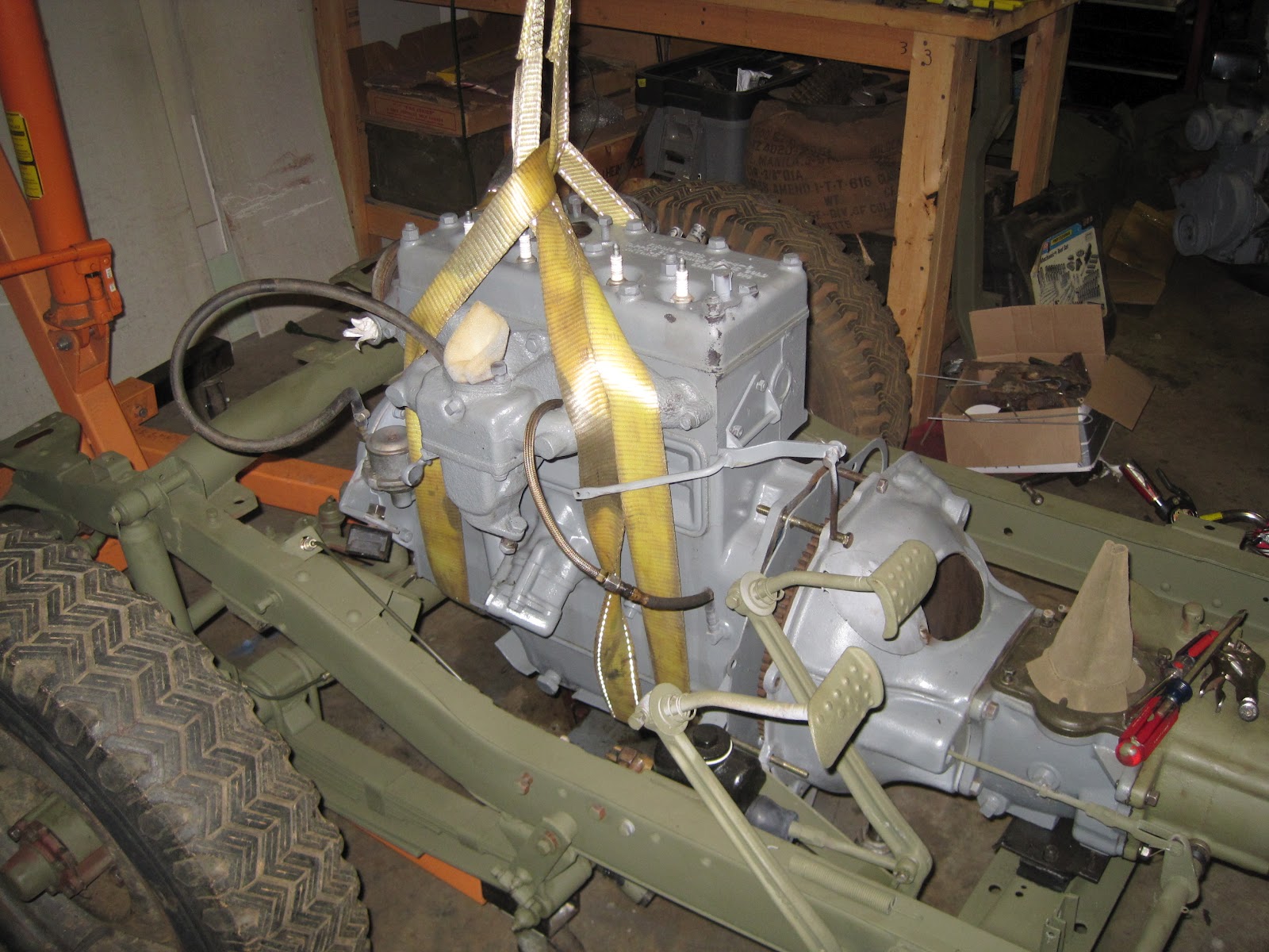
So, getting the engine into the chassis was a bit tougher and somewhat easier than expected.  Let me explain.  I got it up and somewhat in position with relative ease.  However, the tricky part is getting the transmission main shaft to line up perfectly with the clutch grooves.  I was close several times.  Then, like clockwork, Jack showed up and asked what I was doing.  I was in the midst of explaining and showing him the process when the engine clicked and slid into place, sealing the gap of the last inch of space.  I always thing he is my lucky rabbit's foot, and he sometimes thinks that I actually know what the hell I am doing.

I then sorted out all of the bellhousing bolts as well as the two front engine mounts.  I did not use any front engine mount shims, although when I get the radiator in place I am expecting that a pair will be needed to raise the engine a tad.  No, I don't know anything more than you.  It is just a Magnum, PI sort of hunch.

I opted to put the bellhousing and clutch fork in place first.  I could've attached this to the engine and lowered it all in, though.  My reasoning for not doing it was because of the clutch fork.  When the bellhousing is attached to the engine, the clutch fork must then be put in place by utilizing the small inspection cover on top of the bellhousing.  There is zero visibility, scraped knuckles and a lot of sailor swearing involved in that process.

Coming in on final approach.

Close.  Very close.  At this point, my pucker factor has decreased tremendously.

OK, so I lied about the 1" gap.  It looks like it is about 2".  Nonetheless, she isn't going in place at this point.

Boo-Yow.  Jack shows up and ta-da...all is right.

Inspector General inspecting like a Modern Major General.

Just need to screw the bolts down in the front mounts. 
(black rubber block located at the front, left and right bottom of the engine.)
Here is a good shot of removing the engine back in December '11.  This is the postwar CJ/M38 engine.

The engine mounting was performed in the secrecy of the garage Friday night. 
Saturday morning I pushed the chassis with drive train (nice, huh?) into the driveway.

From the front.  Despite what my neighbor thinks, I believe this accomplishment
gets back some of the alleged strikes against my "man-card."
Not quite sure what I was focusing on, but here is my best attempt at the same angle "before" shot. 
It has come quite a ways...

Afterwards, I thought I would do a bit of cleaning and rearranging the garage.  I figured a major portion of the restoration has been completed and it was time to better organize myself.  First off, I needed to switch both jeeps around.  They needed to get back into their respective bays.  I pushed them both into the driveway and then decided to better organize my spare parts.  I unloaded them all from their boxes and laid them across my garage.  I then took my technical manual and reorganized/reclassified them into boxes designated to each respective group...i.e....Group 1: Engine;  Group 2:  Clutch;  Group 3:  Exhaust all the way down the line to Group 26: Radio Suppression.  Yes, it was a HUGE mess, but in the end, it was worth it.  Two or three times I have purchased parts that I already owned.  That is a bit irritating.  This way, when working on a certain component, I can clearly see what inventory I already possess before going shopping.
The BIG MESS prior to organizing.
At this point, I am "accessorizing" the engine with pretty jewelry...the generator (that I rebuilt way back when) and the starter will get mounted.  Also planned is to clean up the oil filter and brackets and to rebuild the carburetor.  All of these items need to be installed before toying with the thought of making it go vroooom.

Monday, May 14, 2012

Door Number 2: The GPW Engine


It is time to get the people's first choice (really, it is just my first choice) engine ready for insertion on the chassis!  The mountain man I bought this from said "I got it running last year."  I guess I'm taking his word for it, but hopefully I can get it up to speed regardless.  Come along and enjoy the ups and downs of this endeavor.  Since I haven't looked inside of it, I have no idea as to its condition.  All I know is that it turns freely...which is a positive start.  I do not know the exact date of this block, only that I have it guesstimated to perhaps late June, 1942.  When I remove the oil pan, there should be a stamped date on the underside which will tell us exactly!
GPW side

GPW rear

GPW front

GPW side

Engine serial number:  GPW 37031.  I think I had this dated to a late June, 1942 Ford jeep.  It may have been in one of the last "Ford Script" jeeps manufactured.  Up until mid '42, Willys and Ford both "branded" their jeeps manufactured with their name on the rear panel (where the spare gas can would eventually be placed).  After mid '42, the government changed the verbiage of the contracts and this practice was discontinued.
Step one is to remove most of the bolt-on items and then I can get down to cleaning up the block so I can see specifically what I am dealing with.  I am hoping beyond belief, that externally, I will not find any surprises.  If that is the case, then we can begin to look internally...

Other known issues is that Bubba has welded all sorts of extra steel parts where the generator should bolt to and one of the ears on the front mounting plate are mangled beyond safe repair.  I have a "new" old usable plate to install.

The twisted and mangled front mount plate and behind and
above it is all of the extra steel bits and pieces welded to the generator bracket.
I cleaned up both sides, the top and the rear of the block.  I am going to wait to do the front portion of it when I disassemble it to replace the front mounting plate.  I removed the oil filler and tappet/valve cover, cleaned and then primed them.  The cover plate had a faint "F" punch mark as well as the early vent system which was just a tube that vented the excess fuel and exhaust vapors below the engine compartment.  The later versions of the jeep engine had a PCV system that would pipe those gases back into the intake manifold to be reused in the engine.  It was/is a more efficient method.  I'm not sure what year this change occurred, but in mid '42, this was still the accepted method.

With the side cover off, I went ahead and just checked the valve clearances.  Remarkably, they were all fine.  Which makes me think I did it wrong.  Jack was napping so I was unsupervised.  The other good thing to note is that all of the valves moved freely and I did not find any broken springs or locks.
Cleaned and primed (L to R) side valve cover plate, front mount plate, vent tube, oil filler spout and dip stick.

Mind the Gap!  Checking the tappet clearance on intake valve, number 1 cylinder.
I did a very rudimentary compression test just because I was curious.  I got 30 lbs. of pressure on each cylinder which is terrible, but I was spinning the crank shaft in a not very efficient manner.  I was using my ratchet and socket.  To be technically correct, I would need to have the starter in place and give it some juice from a battery.  I still may try it, but the starter that fits this flywheel is 12 volts and I am not sure if it in 100% working condition.  It spins when attached to a battery, but something seems askew with it, though.  I need to investigate the starter further.  For now, whatever condition the cylinders are in, they are at least consistant...good or bad.

I removed the six nuts that hold the both flywheels on and with some gentle peruasion with a crowbar and they both finally "popped" off.  The switch was easy, or let me say would have been easy if...if Bubba hadn't had made an "oops."  Evidently, at some point in the GPW engine's life, somebody had disassembled some of it, or perhaps all of it.  When he reassembled the engine, he put the crank shaft back in place, but FORGOT to install the four bolts in the end (the bolts that hold the flywheel in place) BEFORE he installed the crank shaft!  It was evidently after the fact that he discovered his error and in lieu of taking the lower half of the engine apart, he just inserted the four bolts in backwards.  To do this, he had to cut the nuts in half since there is not very much room between the end of the crankshaft and the rear of the engine block.  Jerk.  I can't let this go back in the jeep like it is.  I am going to replace the bolts so they are inserted in the correct direction.  More on that in a little bit.

GPW and script F on the backing plate that is nestled between the flywheel and rear engine block.

View of the rear of the engine minus the postwar flywheel and backing plate.
 The four vacant holes is where the four bolts were inserted backwards.


WWII flywheel mounted.
 (But only temporarily since this is when I discovered the "lack of gap" betweent he nuts and the rear of the engine block.)
 To replace the busticated front mounting plate, I had to remove crank nut, pulley, front cover, oil slinger and then the larger and smaller wheels that hold the timing chain.  Once all of this "stuff" is out, I can reach the remaining hidden bolts that disconnect the front mounting plate from the block.  A gasket sits between the plate and the block, so this had to be scraped clean and a replacement gasket installed before mounting the "new" old mounting plate.
Timing chain on the front of the engine.

Small dot is visible at the 2 o'clock position behind the tooth of the smaller gear.  This should match up with a similiar mark on the larger gear.  That mark was suspiciously absent.

Timing chain is removed as is the busticated front mounting plate.

The surface behind the front mounting plate was covered with the remains of the old gasket.

The old gasket was scraped away, the surface cleaned and is now ready for the new gasket.

New gasket in place with sealer in the rear.

The new front plate is in place and careful attention was paid in replacing it in the exact position that it was originally found.
 Everything was going back in place just fine.  Too fine, actually.  I got it all back on when I discovered that I had THREE "F" marked bolts left over!  Oh, oh.  This is not good.  I kept looking back at my busticated front plate trying to figure out where the three leftovers belong.  Clear as mud, I found it.  There were three bolts that mount the front plate behind the larger, upper timing chain wheel.  I got those confused with the four bolts that connect the timing chain to the cam shaft.  Now who is the jerk?  Me.  I took it all apart, popped the three amigos in and then reassembled everything.  That's how I like to roll...everything twice makes it really nice.

Bubba lent his hand to providing me with one more challenge.  The oil intake nut was plugged shut in the front cover plate.  That can't be good.  The timing chain needs lubrication and it is through this nut that the oil line is connected.  However, I got lucky.  Instead of welding the opening shut, Bubba used solder, and a lot of it!  I literally "fired up" my torch and heated it into a puddle of silver goop.  The internal threads were still intact!  Nice.  The oil line should connect just fine, now.  I then swapped a new seal for the old seal where the pulley is inserted and the cover plate was ready to be primed.
Betcha can't find the upside down "F" mark on the front cover!

The oil intake cap was plugged by Bubba.  Not good.  If you are still looking for the "F" mark, it is visible, but not clearly.

Luckily, the oil intake was plugged with solder.  I just heated it with a flame and it oozed out.
 The solder blob is sitting on the workbench.

The original seal did not look bad, but since the cover plate was off and I had a new seal I figured I should go ahead and replace it.  Old seal out, new seal in!

Oil slinger on the crank shaft and pulley sitting beside it.  When I removed it all, the woodruff key was missing.  It is the small piece of steel nestled in the groove near the end of the crankshaft.  It will fit into the groove inside the pulley and will keep it in place.  I was giddy as can be when I found a perfect replacement in my stash of parts!
I assembled the rest of the parts and closed up the front of the engine.  I drained the oil out of the oil pan.  The reasoning was two-fold.  One, to replace the bolts for the flywheel, it will be easier to flip the engine upside down.  I really don't want 4-5 quarts of oil sloshing around everywhere.  Secondly, who know how old the oil is and what kind of gunk is in it!  The previous owner said he had the engine running last year, but who knows...   After seeing the backwards bolts and the missing woodruff key, I am no longer "assuming" anything on this engine.

To replace the flywheel bolts, the first step is to hoist the engine onto the engine stand.  Once it is in place, I can remove the oil pan and then spin the engine upside down.  To gain access to the four bolts, the bottom portion of the rear main cap is removed.  The bolts are inserted and then the cap is replaced.  The oil pan then needs to be cleaned up both, both internally and externally, as well as the lip that the gasket is sealed against.  While I have access to the bottom of the engine, the oil pick-up will also be thoroughly cleaned. 

So that is the plan in theory.  In practice, it went exactly as planned.  There was some serious "funk" in the bottom of the oil pan so it was a great thing to have it removed.  When I got the engine mounted to the stand and then rotated it upside down, the engine "barfed" up some sort of oily/water mixture out of the oil pump and water neck.  The guy I bought it from said he was dumping oil into it...why, I haven't a clue.  I'll do a proper flushing later.  Enough of the chit-chat.  Here is how the story unfolded in pictures.  I didn't take too many since I was too busy trying to work fast and not panic thinking that my engine block was going to break where the bolts mounted it to the stand.   It held up just fine, but it is old and heavy...just like me...and I worry a lot.  That's why people call me "Whiskers."
Prepare for lift-off.  It has to go up and then slide into the engine stand (left).
 I have already mounted the attaching hardware to the rear of the block.

Phase 1:  Complete. 
And now I have begun worrying that the mounting areas on the block will crack under the amount of load they are bearing.

To get access to the flywheel bolts, the rear seal of the engine needs to be removed.
 I have removed one bolt already, one massive bolt remains.

The rear cap is off and the flywheel bolts installed from the correct side.

Oil pan is cleaned and in place.  I have a lot of newspapers trying to soak up the engine barf.

And now the Eagle has landed...safely...barely.  During the lowering process, I could not get the engine stand to disconnect and the weight of the engine in the straps was off center.  Amazingly, my neighbor walked up at JUST THE RIGHT MOMENT to lend a hand!  Thanks, Joe.

Primed.

Painted Ford grey.  Willys painted their engines OD, Ford painted theirs grey.  I purposely did not paint the water pump.  It has a lot of original, dirty grey that needs a bit of cleaning.  The pump will probably need to be replaced, anyhow.
 The seal is probably shot.
I also have my "once upon a time I forgot to order a rubber brake line" brake line in hand so I think I will tidy the brake system up.  Then we can begin to think about mounting the engine onto the chassis!