Gauges. I've got five in all, and I think three need something above and beyond the call of duty done to help them (besides a new paint job).
Fuel gauge: needs to be opened up and hopefully just solder a few wires together
Speedometer: repair/replace one of the mounting screws on rear
Amp gauge: OK? Hurrah!
Oil gauge: OK? Hurrah!
Temperature gauge: Aye, carrumba. This will take some work...and then it probably still won't work.
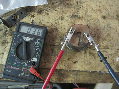
So lets jump right in and fiddle around with the fuel gauge. The first step is to check the resistance between the two poles. They checked out alright. However, when I checked the resistance between the driver's side pole (facing), I came up with an infinite reading. That is not alright. Time to disassemble and investigate.
 |
| Resistance between the poles: CHECK. |
 |
| Resistance between pole and base: Not so good. |
 |
| I used a paint lid pry bar (like a bent screw driver) to get the lip of the cover going and then a screwdriver finished the deal. |
 |
| The last two nuts then were removed. I sprayed a tiny drop of penetrating oil into the center of each. Then, very carefully so not to have the post spin, I unscrewed each nut. |
With everything out, I rechecked the readings. Post to post was just the same and fine. However, post to rear base showed resistance this time! What?! That can't be. I expected to see the fine wires that connect the coils to the screws broken and needing to be re-soldered. Upon close inspection, I double and triple checked these wires...and they were still in place!
 |
| There are two of the fine wires coming together in the center of the picture. |
 |
| You can barely see another one of the fine wires on the right side. It is about the thickness of a piece of hair. |
I was momentarily dumbfounded as to why the gauge wouldn't be working. All appeared to be in place. I picked up the empty case and studied it. Perhaps the back wall needed to be sanded down. After all, it wouldn't hurt to see some shiny metal in that place. These jeeps are wired to a 6-volt system. That is the same voltage most riding lawnmowers run at. Actually, I haven't shopped around lately. I bet many of them are at 12-volts these days! Anyhow, in order for the 6-volt system to work (and to work well!), it is a must for all of the grounding points to be in perfect order. The rear part of the internal section of the gauge has a copper piece that "grounds" into the rear of the case. Then, when the gauge sits in the dashboard, the exterior perimeter of the gauge "grounds out" into the body of the jeep. The body of the jeep "grounds out" into the frame which is connected to the negative (ground) post of the battery.
I sanded down both sides of the rear section of the case and then did a light sanding of the copper part on the back of the internal section of the gauge. I figured I had nothing to lose. Do this, then check the resistance and THEN figure out what the next step will be.
 |
| Internal rear wall of the case after sanding. |
 |
| External rear wall of the case sanded. |
 |
| The the gauge is just sitting in the case and I am checking the resistance between the post and the case. |
 |
| The posts are now screwed in place and I still have resistance. I was a bit afraid that I would brake the delicate wires during assembly. |
The bezel/lid was put back on and I used a pair of pliers to gently close it back in place. One down, two more to go!


No comments:
Post a Comment