Monday, April 16, 2012

Transfer Case, Part Deux (2): FINALE!

When I last signed off, I had dismantled a large chunk of the nastiness that I call "Transfer Case Neglect."  I removed the major components (the main case, front output cap, rear output cap) and disassembled the internals of the main case.  After completing most of the cleaning, I halted.  This was mostly out of fear that I would eventually forget how to put it all back together since I had to wait for parts to arrive and then my family and I traveled to DC for a week.  (Shout out to the Lt. Col and the lawyer!)

Upon return, with parts in hand, it was time to get busy!

First step:  fit the new bearing onto the output shaft.  This is an extremely tight fit, so I had to place it in the 12 ton press.  I didn't want the new bearing to take the brunt of the pressure, so I used the the steel insert part of the old bearing.  It virtually disintegrated when I removed it from the case.  It has the exact same specs as the new one so it sat perfectly under it while the new one pressed on.  It seems very logical to use the old bearing for this job, but for some reason, it took my brain awhile to figure it out!  Bubba would have been shaking his head in disgust at some of my original ideas before this thought developed!
Pushing the new bearing in place.

I started off by putting the components back on the output shaft and getting it back in the case.  To do this, the shifting fork (that puts the jeep in high/low gears) goes in first.  Then, I could fit the output shaft in place.  The hardest part was after the output shaft was in the case, I needed to install the snap ring to hold the gears in place.  During the disassembly phase, it was this snap ring that broke (due to incorrect tools...don't have to worry about that now...THANKS, Colonel!).  I needed a third hand for the install.   I had to keep wedging it up the shaft with the aid of a few screw drivers.  One to lift and push it while the other screw driver held the opposite side in place.  Truthfully, a trained octopus would have been the best option.
The shifting fork.

The output shaft in place.  New bearings and cups, as well as one new snap ring.

Here is a view of the new snap ring.  This is the one that I needed the octopus for.

Nothing of importance to see.  I just wanted to show the mass mess and chaos that I seem to make.
The next item to clean and restore on this hit parade is the front output cap. 
Front output bearing cap:  as a reminder, this is what I started with!

I was a bit intimidated with it, but once I got going, it really is very simple.  Basically, it holds the second shift fork that puts the jeep into four wheel drive.  Out comes the fork, then I tapped out the shaft, and removed the clutch gear. 


The first part that proved challenging was removing the over sized snap ring that keeps the bearing in place.  I ended up soaking the stuck snap ring in penetrating oil for the night.  The next day, I was honestly quite surprised to see it move!  There is a small notch cut into the case that a screw driver fits into and then will act like a wedge to push the snap ring together.  I used the aid of a smaller screwdriver to begin working it out of the channel...and then POP...goes the weasel.  The notch is barely visible in the above picture.  It is in the 3 o'clock position nearest the left shaft.  The clutch gear (the donut looking gear previously was sitting in front of it.

With the snap ring out, I tapped the shaft from the front side and it and the bearing fell out...on the workbench.  What I thought would be the easiest job...removing the three oil seals... proved to be the most difficult.  In the end, I needed a punch, a hammer, a flat headed screwdriver, a chisel and A LOT of patience!  The last thing I wanted, or needed, to do was to scratch the smooth surface that the seals slide into .  All is well that ends well.  In the end, I got 'em!

Front cap with seals removed, internals cleaned and tools used! 

The remains of the larger seal are at the bottom of the picture. 
The two smaller slide rail seals (small holes, left side) are about to meet their maker!

And the small rail seals...destroyed.
 Maybe because Easter is here, I thought the case resembled a scared bunny rabbit...or maybe a monkey?
Putting it back together is just the reverse...I did the seals (used a socket and tapped them in), then the bearing followed by the snap ring.  I seriously was dreading the snap ring, but it turned out to be a cinch.  I think I might specialize in rebuilding this component.  Too bad not everyone needs one.  The shift rail went in and then I slid the gear shaft in place.  The clutch gear and fork assembly all went in together.  I had to line a hole up in the slide rail to meet the screw in the fork.  Once screwed in, a safety wire then tied the screw in place to secure it.
The new and improved inside!  The old bearing is sitting in front.
 I can't even make it spin because it is so gummed up with gunk and rust.


A view from the front.

In my last entry (painting the frame), I mentioned that the missing link-single dust felt seal (the dollar part!)- was the minor part that is keeping me from progressing any further on the transfer case.  Well, Sunday turned out to be a roller coaster of jeep emotions.  Let me recap...

I went to the garage early, 0645, waaaay before any of my family peeps would be out of bed.  I wanted to get a leg up on installing my Speedi Sleeves.  While rummaging through the chaos of my work bench, I was inventorying (for the umpteenth time) my package of transfer case gaskets that I bought several jeeps ago.  (I use the gaskets as templates so I can make my own...yes, I can be that thrifty.)  Low and behold, laying silently in my clear plastic package was a felt dust seal!  Buggers!  I never noticed it before!  Jeep emotional roller coaster = riding high!  Now I can do the whole kitten-caboodle today.  Big plans.
The first thought that ran through my head upon discovery of the felt donut like dust seal was the infamous words of Colonel Klink to Sgt. Schultz, "Schultz, you DUMMKOPF!"
 Despite my stupidity, I am bursting with happy happy joy joy on the inside.
 I got excited with my Speedi Sleeve and didn't take any "before" or "during" pics.  Basically, it is a thin, tight fitting bushing that fits over a worn out surface.  It comes with a cap that is placed over the sleeve and you pound it into place.  Before fitting the sleeve, I filled in the worn groove with an epoxy and coated the inside of the sleeve with a light brushing of non-hardening sealer (like what I use on my gaskets).  Then, once in place, the flange breaks off for an unobstructed surface...to stick my darn felt dust seal.
This is the Speedi Sleeve (silver part) already in place on the front output yoke. 
I still have to break off the flange from the bottom.

Speedi Sleeve (in my hand) coated with the sealer, rear output yoke on the bench.  The yoke sits inside of the parking brake.

Sleeve installed and the flange is being removed.

Front output cap gasket in place.  The rail protruding is the Hi-Low shifter. 
The case is actually laying upside down.

The Front Output Cap is installed and now the poppet balls and springs need to be inserted.  The smaller interlock is already in the case between the two shift rails.  The balls an and springs apply extra pressure to the shift rails to keep them in gear.  There is a hole in the bottom left of this picture. 
One set goes in there and on the opposite side of the case is the second hole for the second set.

The Rear Output Cap shims (resting on the cap) and the speedometer gear (also on the shaft) in place.

The felt dust seal is in position at the base of the yoke and ready to be slid into place on the rear output cap.

The tricky part was reaching the bolts that are tucked inside of the parking brake.  Also pictured is the safety wire that meanders through all of the output cap bolts to help keep them from spinning loose.

Bottom cover gasket in place.
 With the transfer case now fully assembled, I could mate it with the transmission.  The interlock plunger fits between the two cases and must be done prior to bolting them together.  The plunger helps keep the transmission shift rails in gear.  I coated it with a glob of grease to help keep it in place during the final assembly.
Finished transfer case!  The 4-wheel drive and Hi-Low shift sticks will get installed AFTER the tub is mounted on the frame because the hole in the tub will not accommodate the angle that the shift sticks sit.  (Say those last three words really fast!)

The second to last piece of the puzzle is the interlock plunger that fits in he channel between the two nickle-sized holes.  The final piece of the puzzle is installing the large gear, washer and castellated nut that sits on end of the transmission main shaft inside the left side of the transfer case...that same nut that gave me a run trying to remove it!

Shhhh...mating transmission and transfer cases!
With it completed, I was very excited to get the cases mounted on the frame cross member.  Jeep roller coaster meter is running sky high.  Then, I realized that I did not have the right sized bolts to attach it to the mounting plate.  Roller coaster enters a valley.  I run to Lowe's and get the hardware.  Roller coaster climbing.  I get the case perched on the cross member, but I cannot get it to sit level.  I eventually discover another "dummkopf" move.  I've got a darn CJ2A (postwar jeep) transmission cross member installed.  Where the hell were you on that one, David??

I immediately plummet into another valley.  I go to the jeep junkyard (my side yard) and inspect the candidates over there.  A-HA...I've got one...actually, I've got two over there.  The downside is that they are both installed in a jeep WITH the transmission and transfer cases.  Ouch.  Another big, dirty job.

I go inside, take a shower and fall asleep while plotting my course of action.  Upon awaking, I go to the junkyard in my yard and proceed to remove the cross member on jeep #3 (the nastiest one).  I get it down, remove the T90 tranny/transfer combo and get my new cross member. 

CJ2A clean and pretty, but not what I need.  Subtle differences.

Side view is a bit more obvious.  CJ2A on the left, WWII on the right.
Ironically, the main reason I painted the frame was so the cross member would be ready for the trans/transfer cases.  Ha..it showed me.  Due to the annoyance of mixing the paint, I might end up waiting to paint the correct cross member when I paint the tub.  That might give me the incentive I need to fix the last area on the tub.  And ironically, that last area is where Bubba cut out the transmission hump area to accommodate the T90 transmission!  My roller coaster is climbing.

Saturday, April 14, 2012

So "F"ing Happy...Painting!

I really haven't much to report at the moment.  There has been A LOT of hurry up and waiting as of lately.  Like the axles, I have made great strides in the rebuilding of the transfer case and then- KABAAM!- I discover that I have overlooked a minor but somewhat critical piece of the puzzle.  The latest oversight was only ordering one of two semi-necessary felt dust seals that cover up the outside of the output shaft bearings (front and back).  I think with the modern day bearings, I would have been fine without it, but since I have the darn thing apart...might as well set them in. 

The other major fauxpas was neglecting to address the seal wear on both of the front and rear output shaft yokes.  During the last 70 years, the yokes (attached to the drive shafts) would continously spin, thus the leather seals would wear a channel around the yoke shaft.  Now, if I were to install as is, the new seals would not sit tightly on the shafts and I would have a nice oil drip.  The jeep is going to drip oil no matter what, but my goal is at least to make it work at it and not give it a freebie canal to freely flow!  My solution is one of two options:  replace both yokes OR try something I have never done before.  I went for option two.  I am going to try installing a pair of Speedi-Sleeves (thanks to Adam at DriveTrainAmerica.com!)on both yokes.  I've heard success and failure stories.  Wonder which category I will fall into?  Do not worry. I have already started the sequal blog to the transfer case finale blog...I will detail it all for you later!

So, in order to get my $1.00 felt seal, I ordered $99.00 more in parts...you know, to make it "worthwhile" to have it shipped across the country!  As for the "now" while I am waiting for some parts to arrive...I cleaned up a smorgasbord of parts that revolve around the clutch and brake pedals.  Once I get the transmission/transfer case mounted on the frame, I will now be able to cruise right into installing the pedal system.  Fun!  I rummaged through my parts bin and found the stuff I needed...in triplicate, too!  So I went ahead and cleaned them all up, primed and then painted them today.  Now, when the time comes for jeep number two, I am already ahead of the curve.  The other fun part was that I salvaged a few really small parts off of jeep number three to use, too!  I love that.

I got frisky with the chassis, too.  I have a used gallon paint can leftover from the original good jeep's restoration.  The paint is probably 4 years old, I am guessing.  I opened it up and it had separated.  So, I stirred it, and stirrred, and stirred and stirred a bit more.  It looked decent and came back together so I decided to give it a go.  It seems to have worked, too.  I got the frame painted OD as well as my two grills (not sure which one I will use!) along with all of those pedals and such.  I am ready to go now as soon as that felt donut arrives!  The paint was OD 319 if anyone cares.
Mirror imaged?  No, just double the fun.

From LEFT to RIGHT:  OD Green metal stuff.  If you want to get technical, you've got a pair of brake and clutch pedal shafts, brake and clutch tubes, brake and clutch pedals, clutch shaft brace and a steering arm.
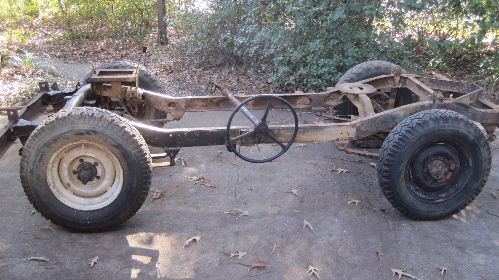
Blast from the past...chassis BEFORE cleanup.

BEFORE profile.

BEFORE rear.
Like Sarah says to me, "Way to knock the rust off of that, baby."
PRIMED front.

PRIMED side.

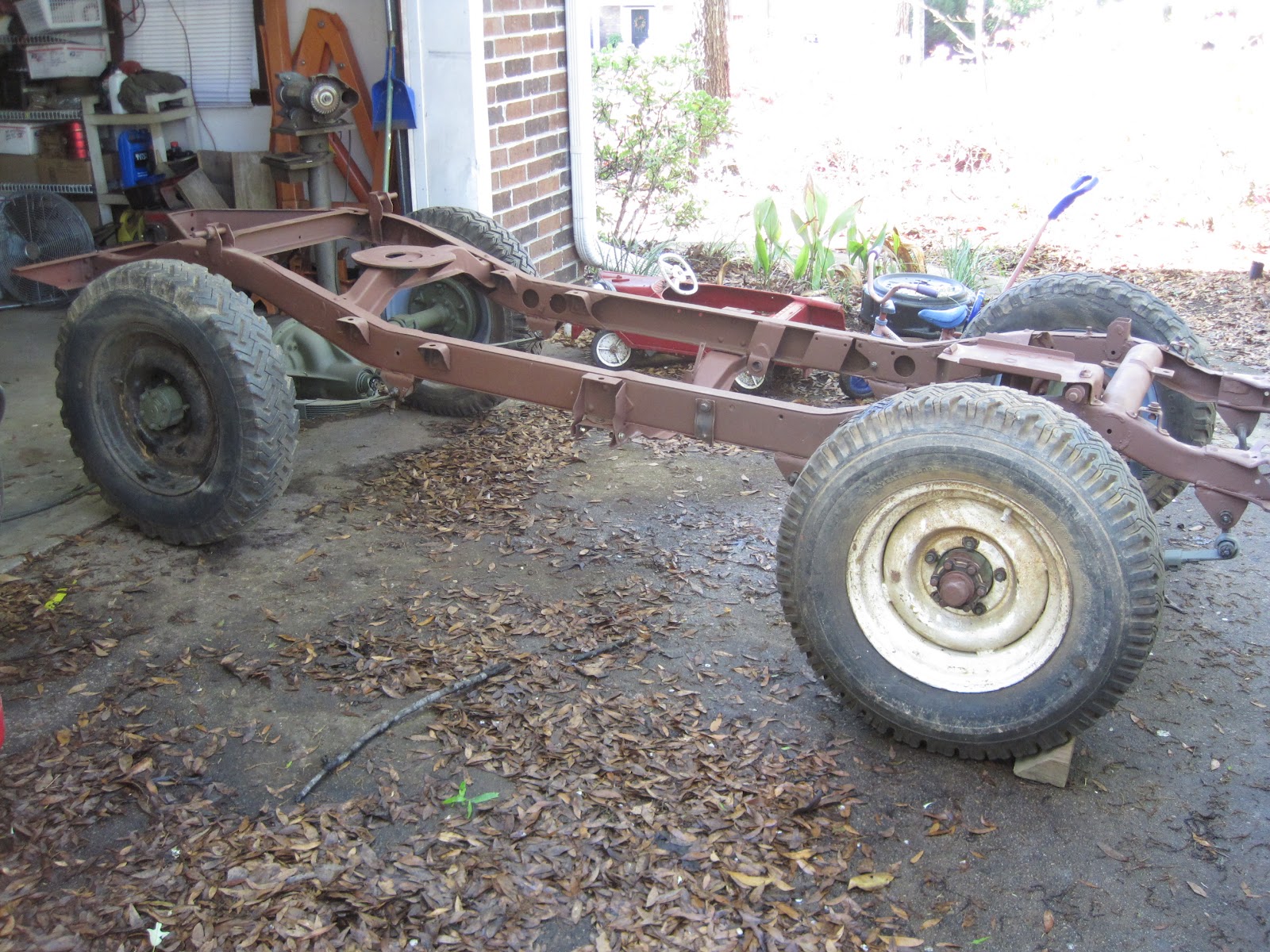
OD rear!

OD front!  I even straightend the frame horns out some.

OD side...well, kind of from the side.  I was too lazy to push it into the driveway.
 Hopefully by this time next weekend, I will have the transfer completed and installed on the chassis.  So that should give you all the incentive you need to make it through the next work week.


Tuesday, March 20, 2012

Transfer Case, Part I

Now with the transmission case relatively complete (waiting to add gaskets until the last moment prior to mating it with the transfer case and engine), it was time to pick out one of my half a dozen transfer cases to clean up.  My five year old son, Jack, will very simply tell you that the transfer case make the jeep go in four-wheel drive.  He is my secret weapon and when I get confused, he dumbs things down so even I can comprehend the most complicated theories.   One day, he and I were chatting about some old theory of Einstein's while enjoying a cup of coffee.  He pointed out to me...sorry, I am getting WAY off track right now.

Anyhow, I thought a Dana 18 transfer case was a  Dana 18 transfer case no matter when it was built (during the war or postwar).  Ha!  I have been somewhat educated in the last week or so.  Although the systems are the same, they are different.  Two major areas of difference are the postwar units had an upgraded Intermediate Shaft (went from .75" WWII to 1.25" postwar).  Also, the beefier T90 postwar transmission was structured slightly different from the WWII T84 unit.  The T90 did not need the critical golf pencil sized Interlock Plunger to rest between the transmission and transfer cases.  So, the postwar units did away with cutting out the channel in the transfer case for the Interlock Plunger to ride in. 

Well, I have several transfer cases (all needing to be refurbished!) sitting around the property, so I really liked my odds of finding the correct WWII version.  In the end, I had two; one still sitting in a dilapidated jeep in the yard and another sitting in the shed.  The one in the shed was easier to access so I opted for that one.  It originally came from the $150 crap jeep I bought locally.  But it is the GPW (Ford) case!  That is a small chunk of gold to me.

The first step in rescuing the transfer case was to disconnect it from the T90 transmission it had been mating with for 5o or so years.  I popped the rear cover off of it, finagled the cotter pin out of the large castle nut on the mainshaft.  For some reason, my 1 1/4" socket was not working.  I drenched the nut with penetrating oil and went to buy a larger socket.  In the end, I used LOTS of penetrating oil, flames, hammers, chisels, screwdrivers and some muscle spread over a week or so, but the darn nut would not budge.  It was rusted on to stay. 

I ended up taking a page out of Bubba's book.  I strapped the transfer case to my trailer, wedged a piece of steel into the gears of the transmission (to stop them from spinning), connected my socket to a breaker bar, stuck the breaker bar into an old fence pole and hung my fat ass off of the pole until something broke.  "Something" was either going to break, as in unfixable, or the nut was going to "break" loose.  I got lucky.
In all regards, this SHOULD work.  Seriously, my muscle with Jack's brains?  Easy.

Struck out with Jack, so I would I was flat out grasping for straws.
Here is the big hunk of steel wedged in the transmission to stop the gears from spinning.
 I wasn't too concerned breaking the gears.  It is a T90 transmission and I have a few of these (that I do not need).

Here is how I actually got the nut to budge.

VICTORY!
Now that I got the transmission and transfer case separated.  It was time to disassemle the case, take inventory, order replacement parts and clean all of the usable materials up.  Let's do this.

Here is the the transfer case with the major componets that I will be referring to labeled.

Rear view.

Front view.

Internal view.  You can see the gears of the Intermediate Shaft.

Front output cap and shaft (bottom left) and bottom access plate (bottom right).

Rear view.  Output shaft and the parking/emergency brake.

Parking/Emergency brake unit.

Internals.   Output shaft (right) Intermediate Shaft (center).

Inside the Main Output Shaft cap.

The nastiness of the inside of the bottom access plate.
I used a 12 ton press to get the Intermediate Shaft out.  Funny thing, on the top of the case, there is a data plate from Brown/Lipe Spicer.  The case clearly has the Ford stamping on it.  This is confliction in the highest sense!  Turns out, the Intermediate Shaft was of the larger postwar variety.  My best conclusion was that the military sent the case back to Spicer after the war to have it modified.

After getting the Intermediate Shaft out, I could then turn my attention to the Output Shaft.  That one was a bit tricky.  I couldn't finesse it out so I turned to the manual to figure out the proper method.  Turns out you  need to beat the rear end of the output shaft with a mallet.  It would then break through the races and cones of the front side and give one room to manuever.  Wow.  I never would have guessed that!  I accomplished this feat, although somewhat skeptically.  The last obstacle was a rinky-dinky little snap ring.  I ended up spreading the snap ring too far and snapped it two.  Luckily, when I was ordering my new parts, I had enough forward thinking sense in my brain to ordered a spare.  Actually, Jack told me to do it.
Output shaft on its way out!

Cleaned and primed main case.

Compare and contrast of the gears.  Can you guess which one I have cleaned?
I ordered $175 worth of replacement parts.  This consists of all of the bearings, seals, cones, races and a few other little parts.  Luckily, nothing of major importance was ruined on the inside.  Everything that is being replaced SHOULD be replaced after 60 years of use and abuse.  When the new parts arrive, I will take apart the other assemblies (front and rear caps), clean them up and then rebuild them.  For now, I am just going to clean up these parts that I am going to reuse...and wait!

Wednesday, March 14, 2012

Axle F(ront)- COMPLETED!

Wow, this project has been going on for several weeks and I think it is finally finished!  For awhile, I didn't think the end of it would ever come in sight.  The delays resulted from not once, but twice I failed to order the replacement parts I needed and then the final delay occurred when I couldn't get the steering pivot arms to "pop" off of the tie end rods so the proper preload tension could be set up.  Oh, don't worry, I do not talk like this all of the time.  I only just read the section in the manual that explained it all to my simpleton mind.  But enough of the chit chat, let's figure out how I got from point A to point D.  A is for Arsenal; D is for Democracy.  I have now nicknamed my garage the "Arsenal of Democracy."

The inside of the axle after all of the seals have been replaced.

Recap...I had removed the main gears out of the axle so I could replace the pertinent oil seals for the axle shafts.  The gears were then replaced after installing the new pinion seal.  Then I had to replace the fourupper and lower cones and cups(fancy words for bearings and the saucers they sit in) on the steering knuckles (the large roundish balls at each end of the axle shafts).

The old (on top) and the new (in place on the bottom).

This is how it looks with the new spindle bearing cups.

At this point, I now needed to install both axle shafts and then I could set up the steering pivot arms.  However, this is when I had a devil of a time trying to separate them from the tie end rods.  Several sources say I could beat on them with a BFH and it would "pop" off due to the tapered rod that holds them together.  Well, I beat, and beat, and beat it like it was the neighbor's red-headed step child.  This didn't work.  I even youtubed some videos of this procedure to make sure I was hitting it right.  I was.  Another source offered up a "pickle-fork", but I feared this would have destroyed my useable tie-end rods, so I opted to continue beating the pivot arms.  One day, many days into the beatings, it all of a sudden, quite unexpectedly "popped!"  Boy, was I stunned.  Nonetheless, I could now move forward.

The next, and supposedly very critical step was to set up the pivot arms with the correct amount of shims in order to get the proper bearing preload...whatever the hell all of that means.  The manual said to do it, so I was game.  I greased up the new bearings, taking great care to keep them clean of dirt and crud, and placed them in the new cups on the knuckles, then I placed the spindle housing on the knuckle and lined up the tapered shafts of the pivot arms to hold it all in place.

Basically, the pivot arms that hold the steering rods connect to those cones and races that I replaced earlier.  Depending on how they were manufactured (thickness and height) one needs to either add or subtract shims beneath the pivot arm to set the proper amount of restriction in its movement.  The manual says to start with .048" of shims on the upper and lower pivots for each side of the axle.  Then, one must measure the pounds of pressure needed to make the pivot arm move the steering knuckle.  The idea pressure is no less than 4 pounds and no more than 6.  In order to achieve this specific rating, more or less shims are required.

If you are raising your eyebrows right now (because you understand what I just wrote) I cannot fault you.  I certainly raised mine SEVERAL times.  No way could these little shims make any difference.  At one point, when I couldn't separate the pivot arm from the tie rod end, I thought about skipping this step.

Meauring the thickness of one of the shims. 
Behind, on the work bench, are other shims of various thicknesses.

This size shim ended up being the shim of choice in order to obtain the proper amount of spindle housing tension.  Ironically, it was within .005" of the shims I removed during the teardown.

The shim pack came with multiple shims in 3 or 4 different widths.  I started out with the required combination of .048" thickness, but when I tested the tension, it was practically non-existent.  I was working on the shorter axle side and when I disassembled it all originally, there were no shims present.  I seriously thought again, "Let's skip this nonsense."  However, I tried one more time, reducing the amount of shims upper and lower.  At this point, it was kind of like a trial and error exercise, however, you needed to keep the shims in the same thickness for both the upper and lower sides.  So I loosened the nuts and gently rapped my hammer on the base of the pivot arm and it slowly made its way out.  I reduced the shims and put it all back together and measured.  Sure enough, there was a bit more drag present.  Wow, it was actually working!  This process when on a few more times...too much, too little and so on and so on.  Finally, I got the right combination.  I ended up using one shim for each mount and it was the one pictured above: .0105. 

Ironically, on the long axle shaft side, there originally was a shim in place.  It measured within .005" of the new one I ended up installing to give it the correct tension.  I still have to fill the internals of it all with grease.

Checking the pivot arm tension.  The camera flash was too bright, but it reads 5.5 lbs when the pivot arm began to move.  The manual gives a range of 4-6 pounds, so this is within spec.

With both pivot arms in place and correctly mounted, I could now put on the rest of the steering gear.  Easy peasy.  Lastly, I lubed up the axle cover with some sealer, smeared it on good and messy, placed the gasket on and then sealed up the main pumpkin.  All it needs now is some oil.

Next comes the spindle, which fits tightly into the housing.  When the brake backing plate gets screwed-in, the screws go through the backing plate, through the spindle and tighten into the knuckle housing.  The sneaky part is tapping the spindle into place, yet keeping all of the screw holes lined up.  To do this, I stuck the screw into the spindle, lining them up with the house and turning them in a few twists.  Then I rapped it gently with a hammer to wedge it into its final spot.  The screws were removed and the brake backing plate was then installed with the screws going into their final resting place.
Spindle cap held in place with loose screws.
The brake backing plate in place over the spindle and all screws tightly in place.

Most of the remaining steps are almost identical to what occurred with the rear axle as far as installing the brake shoes, adjusting them to the drums.  Also required are new seals for the drums, and if required, new bearings and grease.
BEFORE.
I love "before and after" shots.
AFTER!
Both sets of brakes shoes in place.
 (I cheated,though.  This is the driver's side.) 
With both brake backing plates with brake shoes and wheel cylinders in place, the next step is to install the brake hub.  However, before this could be done, I had two more oil/grease seals to replace on each hub.  Also, there are a pair of wheel bearings inside of each hub.   After popping out the seals, I could then remove the bearings.  I cleaned each bearing up (removing what Jack calls "nasty old grease") and then I could inspect them for over-heating marks and individual worn out bearings.  They appeared satisfactory so I packed them solid with new grease, put them back in place and then "gently persuaded" (with a hammer) the new seals.  Hubs installed!
Both hubs with newly grease-packed bearings and new seals (in the center of these metal donuts). 
The red gunk is the new grease.

These large washers go between the big nuts that keep the outer wheel bearings on the brake hubs in place.  The broken washeron the RIGHT came out of the front axle.  The washer on the LEFT is a replacement washer I pulled from an old, nasty post-war jeep chassis in my yard.  I was saddened that I couldn't use my original "F" marked washer.  However, my Christmas Miracle happened in during the Ides of March...the washer I pulled from the post-war chassis was "F" marked, too...An original WWII Ford part!  It is hard to see, but if you look close enough - like put your nose up to the computer screen close - you can identify both "F" marks at the 12 O'Clock high positions.


Both brake hubs installed.  Two more steps to go.
 After adjusting the brake shoes, the last major project to address is the grease seals that sit behind the steering knuckles.  The new seals are a slightly different set-up than the originals.  Albeit a better set-up, they do look slightly different when installed.  In an effort to take advantage of newer technology, yet keep the 1944 look, I modified the original steel plates (which kind of broke my heart) to retain the right "look."

The newer style pressed steel plate (L), the original unmodified plate (C) and the modified original steel plate (R).  Can't see the modification, can you?   Look closely...there is a pin located at the 12 o'clock, 9 o'clock and 6 o'clock positions that must be ground smooth in order for the plates to fit snug against the felt.  Pins are visible on the center plate and have been removed on the right plate.

The seal all assembled.
The only major difference between this set-up and the original style would have been a second set of gray plates mounted behind this one and they sandwiched together the grease seal.  This style has a rubber seal mounted tightly against the knuckle ball joint, then a piece of thick felt and then the original steel plate holding it all together to the knuckle. 

My inspiring mental moment occurred when I was fitting the seal on the long side of the axle.  I had forgotten that when I removed the original, there were only 7 of the 8 bolts present.  Well, when I discovered that fact, again, I felt a bit of dispair.  "Oh, this sucks...gotta go to Lowes for one lowsy bolt to finish this project."  And then, that energy saving light bulb in my head began to emit light.  The light got brighter and brighter and then I realized I was forming a thought.  "Duh, you've got a junkyard outside.  Go get a nut from one of those buckets of rust!"  And that is what I did.  I pulled the correct sized nut off of the old M38 front axle.  That way I wouldn't have to chase down another nut for the next WWII jeep!  That was totally a two for one thought.

All assembled, front view.

All assembled, side view.
I'd like to claim El Finito at this point, but it is fairly obvious that I still have some painting to do.  Internally, I need to fill the pumpkin with oil and the knuckles need some grease.  The grease zerks on the steering arms need a shot of lube, too.  (That lube is for you, J2).  I still need to tighten the two tie rod end castle nuts and the pinion nut.  And I just remembered that I need to pull both axle flanges off and bend the lip of the outer washers over the edge of the outer nuts.  Yeah, quite the punch list.  I'm done blogging about this beast, though.  Next time you see it, it will be mounted to the frame!